Flashing Coreboot on the T430 with a Raspberry Pi

Coreboot is an Open Source project, which replaces the proprietary BIOS of a traditional computer. Coreboot initialize the Hardware and then executes a payload (e. g. SeaBIOS or Grub).
Warning
- The procedure of flashing coreboot could lead to a bricked notebook, only proceed with this guide if you know the risks!
- Only attach wires with removed battery and power not connected to the Raspberry Pi!
Things required
- Lenovo ThinkPad T430
- Raspberry Pi (In this tutorial version 3 is used)
- SO8 test clip or a soldering iron (e.g. Pomona SOIC8 5250 Test Clip)
- 8x Female Jumper Wire
- Another computer to communicate with the raspberry pi
ThinkPad T430 Disassembly
I will not go into detail for the disassembly of the Thinkpad T430.
There are already enough tutorials and YouTube videos online.
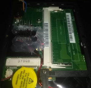
To flash coreboot on the T430 the motherboard should be completely removed, to have access to the bios flash chips.
Getting started
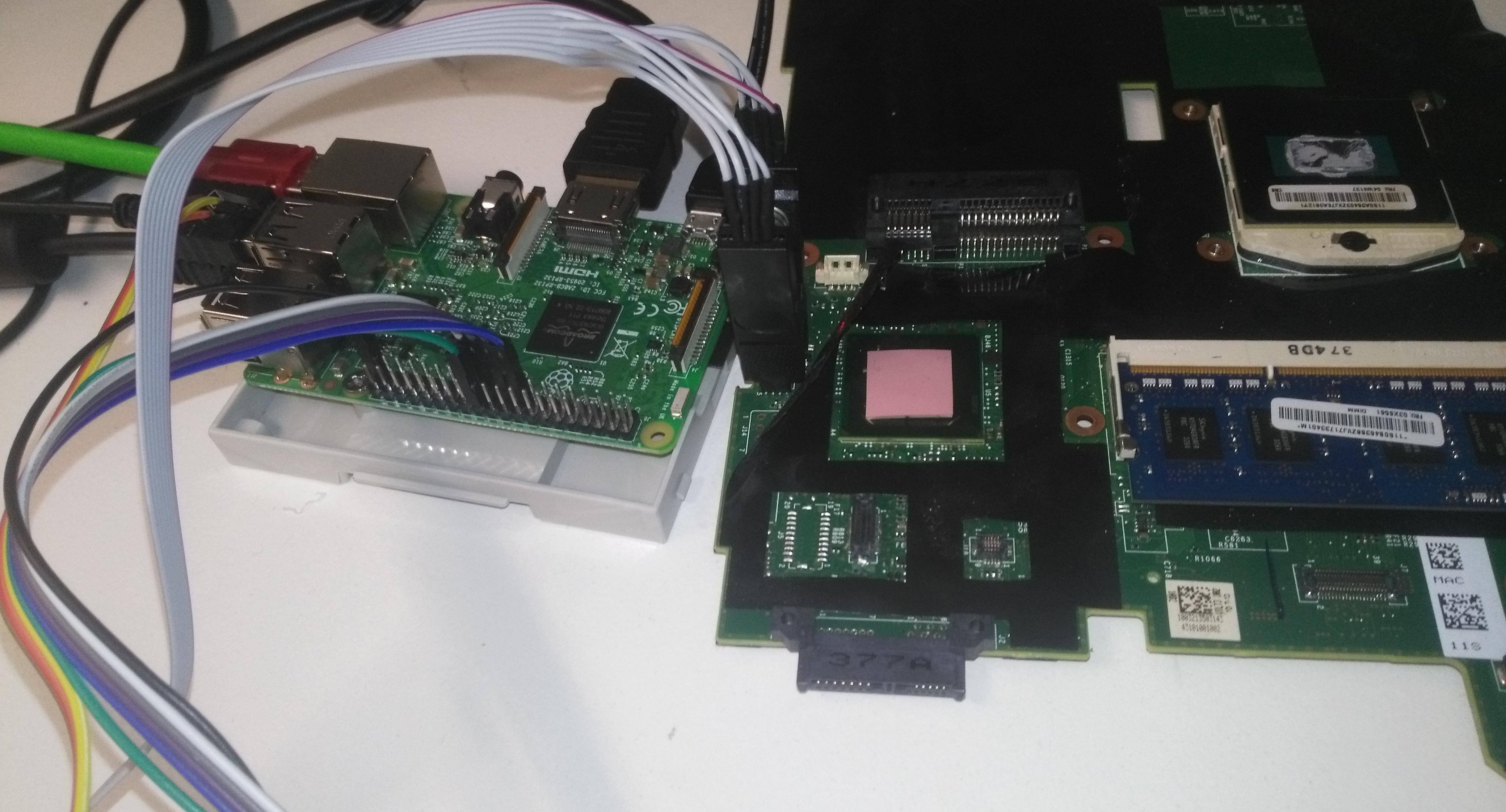
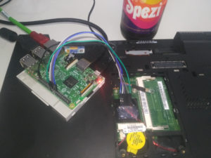
In this tutorial a Raspberry Pi is used to flash coreboot.
Update the Raspberry Pi.
$ sudo apt-get update
$ sudo apt-get dist-upgrade
Install the required software.
$ sudo apt-get install libftdi1 libftdi-dev libusb-dev libpci-dev \
m4 bison flex libncurses5-dev  libncurses5 build-essential pciutils \
usbutils libpci-dev libusb-dev libftdi1 libftdi-dev zlib1g-dev subversion \
libusb-1.0 gnat-4.9 gnat wget zlib1g-dev
Get flashrom, build it and install it.
$ git clone https://github.com/flashrom/flashrom
$ cd flashrom
$ make
$ sudo make install
Modprobe the SPI driver.
$ sudo modprobe spi_bcm2835
$ sudo modprobe spidev
Enable the SPI device on the Raspberry Pi.
$ sudo raspi-config
> 5 Interfacing Options  Configure connections to peripherals
> P4 SPI         Enable/Disable automatic loading of SPI kernel module
> Would you like the SPI interface to be enabled?
> Yes
$ sudo reboot
Read the current proprietary BIOS from the flash chips
Now it is time to read the proprietary BIOS blob from the Lenovo T430.
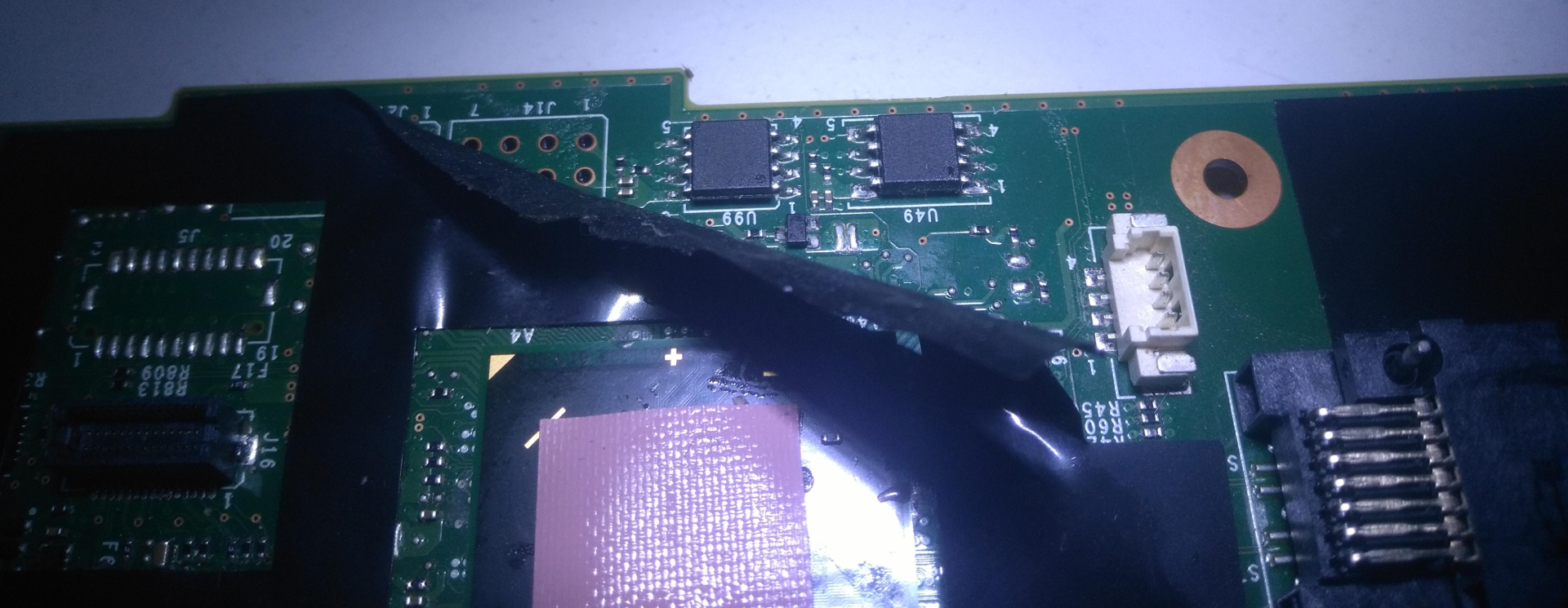
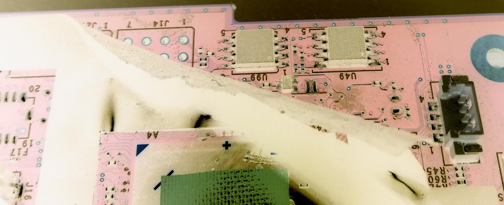
There are two SPI flash chips on the motherboard.
U46              U66
MXIC MX          winbond
25L3206E         26064FVSIG
M21-12G          1317
3L860700
K131576
Pinlayout of the SO8 SPI Chips
            __
  MOSI  5 =|  |= 4  GND
   CLK  6 =|  |= 3  NC
    NC  7 =|  |= 2  MISO
   VCC  8 =|_*|= 1  CS (dot on top of the chip)
Pinlayout of the Raspberry Pi
e       +-----+
d       | o o <-  GND
g       | o o |
e       | o o |
        | o o |
o       | o o |
f       | o o |
        | o o |
R       | o o |
a  CS  -> o o <-  CLK
s       | o o <-  MISO
p       | o o <-  MOSI
b       | o o <-  3.3V
e       | o o |
r       | o o |
r       | o o |
y       | o o |
        | o o |
P       | o o |
i       | o o |
        | o o |
        +-----+
Read from the 8MB flash (UE46)
Check if flashrom detects the flash chip.
$ sudo flashrom -p linux_spi:dev=/dev/spidev0.0
flashrom v0.9.9-47-gaa91d5c on Linux 4.9.35-v7+ (armv7l)
flashrom is free software, get the source code at https://flashrom.org

Using clock_gettime for delay loops (clk_id: 1, resolution: 1ns).
Found Winbond flash chip "W25Q64.V" (8192 kB, SPI) on linux_spi.
No operations were specified.
I am a very paranoid person, so dump the flash three times.
$ sudo flashrom -p linux_spi:dev=/dev/spidev0.0 -r flash01.bin
flashrom v0.9.9-47-gaa91d5c on Linux 4.9.35-v7+ (armv7l)
flashrom is free software, get the source code at https://flashrom.org

Using clock_gettime for delay loops (clk_id: 1, resolution: 1ns).
Found Winbond flash chip "W25Q64.V" (8192 kB, SPI) on linux_spi.
Reading flash... done.
$ sudo flashrom -p linux_spi:dev=/dev/spidev0.0 -r flash02.bin
flashrom v0.9.9-47-gaa91d5c on Linux 4.9.35-v7+ (armv7l)
flashrom is free software, get the source code at https://flashrom.org

Using clock_gettime for delay loops (clk_id: 1, resolution: 1ns).
Found Winbond flash chip "W25Q64.V" (8192 kB, SPI) on linux_spi.
Reading flash... done.
$ sudo flashrom -p linux_spi:dev=/dev/spidev0.0 -r flash03.bin
flashrom v0.9.9-47-gaa91d5c on Linux 4.9.35-v7+ (armv7l)
flashrom is free software, get the source code at https://flashrom.org

Using clock_gettime for delay loops (clk_id: 1, resolution: 1ns).
Found Winbond flash chip "W25Q64.V" (8192 kB, SPI) on linux_spi.
Reading flash... done.
Compare the checksum of the three dumps.
$ md5sum flash*.bin
60e2d8334870e1647653102f19721b8a  flash01.bin
60e2d8334870e1647653102f19721b8a  flash02.bin
60e2d8334870e1647653102f19721b8a  flash03.bin
Read from the 4MB flash (UE66)
sudo flashrom -p linux_spi:dev=/dev/spidev0.0
flashrom v0.9.9-47-gaa91d5c on Linux 4.9.35-v7+ (armv7l)
flashrom is free software, get the source code at https://flashrom.org

Using clock_gettime for delay loops (clk_id: 1, resolution: 1ns).
Found Macronix flash chip "MX25L3205(A)" (4096 kB, SPI) on linux_spi.
Found Macronix flash chip "MX25L3205D/MX25L3208D" (4096 kB, SPI) on linux_spi.
Found Macronix flash chip "MX25L3206E/MX25L3208E" (4096 kB, SPI) on linux_spi.
Found Macronix flash chip "MX25L3273E" (4096 kB, SPI) on linux_spi.
Multiple flash chip definitions match the detected chip(s): "MX25L3205(A)", "MX25L3205D/MX25L3208D", "MX25L3206E/MX25L3208E", "MX25L3273E"
Please specify which chip definition to use with the -c  option.
In this case the “MX25L3206E/MX25L3208E” is on the motherboard.
Same here.. I am a very paranoid person, so dump the flash three times.
sudo flashrom --programmer linux_spi:dev=/dev/spidev0.0 --chip "MX25L3206E/MX25L3208E" -r flash01b.bin
flashrom v0.9.9-r1955 on Linux 4.4.10-1-ARCH (armv7l)
flashrom is free software, get the source code at https://flashrom.org

Calibrating delay loop... OK.
Found Macronix flash chip "MX25L3206E/MX25L3208E" (4096 kB, SPI) on linux_spi.
sudo flashrom --programmer linux_spi:dev=/dev/spidev0.0 --chip "MX25L3206E/MX25L3208E" -r flash02b.bin
flashrom v0.9.9-r1955 on Linux 4.4.10-1-ARCH (armv7l)
flashrom is free software, get the source code at https://flashrom.org

Calibrating delay loop... OK.
Found Macronix flash chip "MX25L3206E/MX25L3208E" (4096 kB, SPI) on linux_spi.
sudo flashrom --programmer linux_spi:dev=/dev/spidev0.0 --chip "MX25L3206E/MX25L3208E" -r flash03b.bin
flashrom v0.9.9-r1955 on Linux 4.4.10-1-ARCH (armv7l)
flashrom is free software, get the source code at https://flashrom.org

Calibrating delay loop... OK.
Found Macronix flash chip "MX25L3206E/MX25L3208E" (4096 kB, SPI) on linux_spi.
Compare the checksum of the three dumps.
$ md5sum flash*b.bin
76b424b99dd6fee6f4246db4c4f311ff  flash01b.bin
76b424b99dd6fee6f4246db4c4f311ff  flash02b.bin
76b424b99dd6fee6f4246db4c4f311ff  flash03b.bin
Extract the binary blobs
,
The two dumps have to be merged in the order 8MB+4MB.
cat flash01.bin flash01b.bin > flash.bin
Cloning the coreboot git. and recursively clone the necessary other gits.
$ git clone --recursive https://github.com/coreboot/coreboot
$ cd ~/coreboot/3rdparty
$ git clone http://review.coreboot.org/p/blobs.git
Build and install the extraction tool for the binary blobs.
$ cd ~/coreboot/util/ifdtool
$ make
$ sudo make install
Copy the binary blobs to the build directory of coreboot.
$ cd ~
$ ifdtool -x ~/flash.bin
$ mkdir -p ~/coreboot/3rdparty/blobs/mainboard/lenovo/t430
$ cd ~/coreboot/3rdparty/blobs/mainboard/lenovo/t430
$ mv ~/flashregion_0_flashdescriptor.bin descriptor.bin
$ mv ~/flashregion_2_intel_me.bin me.bin
$ mv ~/flashregion_3_gbe.bin gbe.bin
Configure coreboot
$ cd ~/coreboot/
$ make nconfig
This is one possible configuration
general
    - [*] Compress ramstage with LZMA
    - [*] Include coreboot .config file into the ROM image
    - [*] Allow use of binary-only repository
mainboard
    -  Mainboard vendor (Lenovo)
    -  Mainboard model (ThinkPad T430)
    -  ROM chip size (12288 KB (12 MB))
    -  (0x100000) Size of CBFS filesystem in ROM
chipset
    - [*] Enable VMX for virtualization
    -  Include CPU microcode in CBFS (Generate from tree)
    -  Flash ROM locking on S3 resume (Don't lock ROM sections on S3 resume)
    - [*] Add Intel descriptor.bin file
      (3rdparty/blobs/mainboard/$(MAINBOARDDIR)/descriptor.bin) Path and filename of the descriptor.bin file
    - [*] Add Intel ME/TXE firmware
      (3rdparty/blobs/mainboard/$(MAINBOARDDIR)/me.bin) Path to management engine firmware
    - [*] Add gigabit ethernet firmware
      (3rdparty/blobs/mainboard/$(MAINBOARDDIR)/gbe.bin) Path to gigabit ethernet firmware
devices
    - [*] Use native graphics initialization
display
    - (nothing checked)
generic drivers
    - [*] Support Intel PCI-e WiFi adapters
    - [*] PS/2 keyboard init
console
    - [*] Squelch AP CPUs from early console.
      [*] Show POST codes on the debug console
system tables
    - [*] Generate SMBIOS tables
payload
    - Add a payload (SeaBIOS)
    - SeaBIOS version (master)
    - (3000) PS/2 keyboard controller initialization timeout (milliseconds)
    - [*] Harware init during option ROM execution
    - [*] Include generated option rom that implements legacy VGA BIOS compatibility
    - [*] Use LZMA compression for payloads
debugging
    - (nothing checked)
$ make crossgcc-i386 CPUS=4
$ make iasl
$ make
Important note: Be sure to have enough space left on the Raspberry Pi.
Furthermore the compiling process on the Raspberry Pi takes a lot of time…
If you want to speed up, compile it on a standard computer.
It is only necessary to flash the 4MB flash UE66. So extract the last 4MB out of the coreboot rom.
$ dd if=build/coreboot.rom bs=1M of=/tmp/t430.rom skip=8
Flash the 4MB UE66 with the extracted 4MB coreboot rom.
$ sudo flashrom --programmer linux_spi:dev=/dev/spidev0.0 --chip "MX25L3206E/MX25L3208E" --write t430.rom
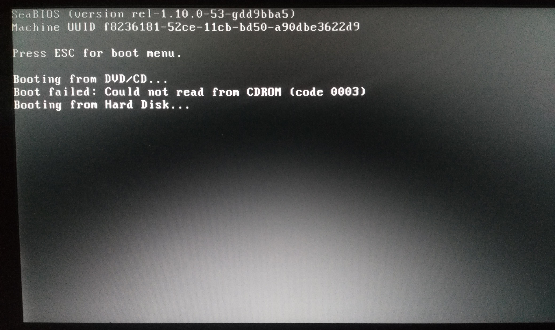
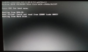
Booting Coreboot with SeaBIOS payload
If everything went well, the Thinkpad T430 is ready to boot coreboot.
Image of the booting process:
Short video of the booting process (very unspectacular):
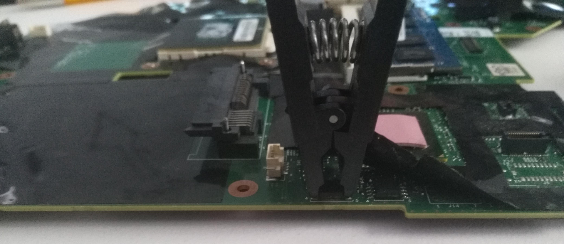
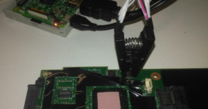
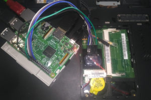
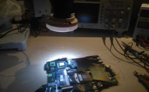
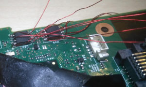
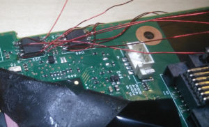
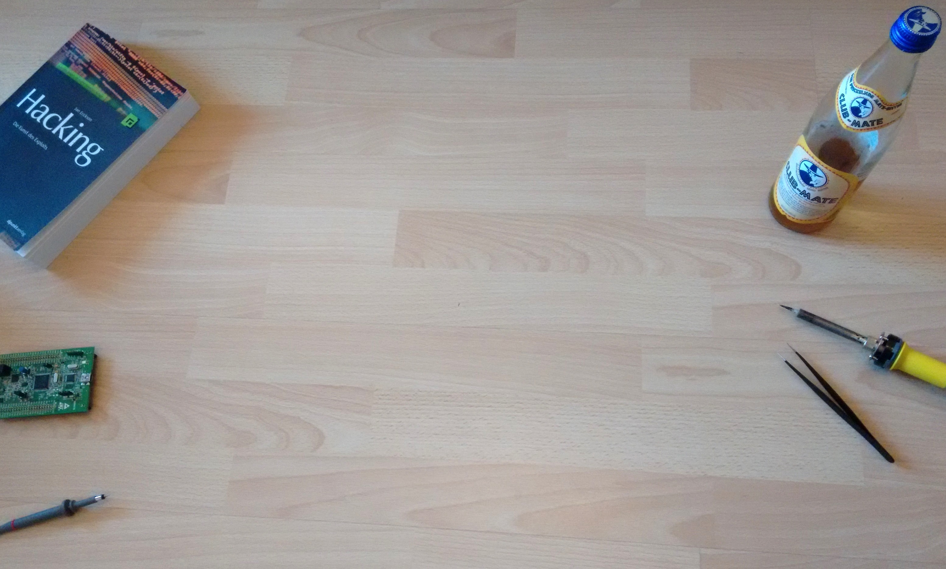
Some images
Just some images I have done.
Furthermore I have wired the flash chips to the maintenance flap, which is not necessary!
Problems
Error extracting binary blobs
If the idftool has an error message in the output, possible problems could be the dump of the proprietary BIOS was not successful or the two dumps have not been merged (8MB + 4MB).
ifdtool -x flash01.bin
File /home/pi/flash01.bin is 8388608 bytes
Flash Region 0 (Flash Descriptor): 00000000 - 00000fff
Flash Region 1 (BIOS): 00500000 - 00bfffff
Error while writing: Success
Flash Region 2 (Intel ME): 00003000 - 004fffff
Flash Region 3 (GbE): 00001000 - 00002fff
Flash Region 4 (Platform Data): 00fff000 - 00000fff (unused)
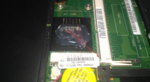
The Laptop does absolutely nothing
After I reassembled the laptop it does absolutely nothing. The fan was not rotating and the power led was off.
I disassembled it again and found a short circuit by two pins of a plug.

Get help online
- https://www.coreboot.org/Welcome_to_coreboot
- Very friendly people in the IRC: http://webchat.freenode.net/?channels=coreboot
- Mailinglist: https://www.coreboot.org/Mailinglist
Hello there! what benefits do you see on doing this?
Nice! I’ve used your tutorial to successfully nab my T430 firmware. I’ve extracted the ME, IFD, Gbe, etc.. Does this 12MB image contain the EC firmware? In the Coreboot config above, you use the ME and GBe but I don’t see the EC option?
Hi and thank you for the awesome manual.
I have a question. Can i use professional SPI Flasher MiniPro TL866CS and Pomona Clip instead of the reaspbery Pi to flash the T430?
I think it should be possible.
And a second question:
Is it possible to combine Coreboot with the Patch for the Embedded Controller to use the Classic Keyboard from T410/T420 Series:
https://github.com/hamishcoleman/thinkpad-ec
Should i build the Embedded Controller in the Coreboot, or should i let it and patch it afterwards?
Thanks
Sounds interesting. I will try it in February when I have more time.
Hi ,what a great tutorial!Right now I am thinking about installing coreboot on a x200 ,but i am a bit puzzled by some instructions,because they are not as comprehensive and easy to understand like yours,and I never installed coreboot anyway.Could you make a tutorial for installing coreboot on a thinkpad x200, please ?
Hi, I’m getting chip read write protected on 1st chip & not recognized on the second. Also Flashrom is saying chip is unsupported. I’m using pi b+ on the latest everything. Do you think because I’m on latest bios? Also mine has Nvidia, do u think that could be my problem? Thanks for awesome guide.
Finally got it built although I had to use a ch341a programmer since flashrom kept saying unsupported. Thank you for your guide.
Hello,
the picture shows the u99 and u49 bios chip, but the discription says UE46 and UE66 flash chips. Is there a difference? I have the t430 with the shown u99 and u49 bios chip. could i use the pinlayout? in google i found the t430 has a MX25L6405 bios chip and the datasheet shows a different pinlayout. i´m a bit confused, for any help i would be thankful.
I took my T430 apart like you normally would to flash it. There is a spot for a dediprog EM100 header on the board under some plastic. I soldered in an ultra low profile header and cut away some of the metal frame/shielding above it with a Dremel tool. Now I can just take the keyboard cover off whenever I want to reflash it. Next tool a 8pin soic to DIP adapter PCB and soldered a new flash chip down to it. I then glued a small female low profile header to the back,cut some of the traces on the adapter and wired it up so that it will force hold active on the onboard flash and inactive on the flash on the adapter. Now I have a removable flash device I can program outside the system then plug in and go with whenever I need to. If I screw something up. That way I dont have to screw with the on board bios.
hi.i am currenlty working with my me_extracted_rom(12 mb).but i always get an error message.if i send to you my me.bin gbe.bin desciptor.bin,will you build a rom like your configration and settings?
To samuel holland…..
Are there any changes in code mentioned in this tutorial…when using ch341a and for nvidia including
Hi, followed the above instructions and was able to get my t430 booting out of SeaBIOS into a current kali install. However, the wifi interface has been hardware rfkilled which I’m assuming must be happening during BIOS. interface shows up as wlan0 in DOWN state but can not be manually set to up. I also additially ran me_cleaner on the management engine bin during the build process. Was wondering if you could give me any guidance on how to debug this. Thanks